



A systematic approach with the right tools turns a potentially day-long wire fault diagnosis into a two-hour repair.
Wire faults in two-wire decoder irrigation systems can appear daunting. The wire path runs underground, and the symptom (a zone or section not responding) does not tell you where the problem is. A structured diagnostic approach eliminates the guesswork. With the right tools and a method for dividing the wire path into testable segments, most faults are locatable and repairable in a single visit.
Tools You Need
Fault finder: A dedicated irrigation fault finder sends a signal along the wire path and helps isolate the location of shorts and open circuits.
Clamp meter: The clamp meter is the primary diagnostic instrument. It measures current on the wire without cutting it, which means you can identify which segment of the wire path contains the fault before making a single cut.
Wire stripper: Needed for splicing after the fault is located.
Direct burial wire connectors: Grease-filled connectors are the correct connector type for any splice that will be buried or exposed to moisture.
Locating the Fault: The Halving Method
Start at the controller and test all major branch junctions with the clamp meter. A higher-than-expected current reading on a branch confirms a short somewhere along that path. An open circuit (no current) on a branch points to a break.
Before testing, confirm the manufacturer's baseline current specifications for the system. Your readings need a reference point to be meaningful.
Once you have identified the affected branch, use the halving method to pinpoint the fault location. Test the midpoint of the affected segment. The reading tells you which half contains the fault. Test the midpoint of that half. Repeat until you have narrowed the location to a workable section. Document each reading and location on a rough sketch. This becomes part of the system record and simplifies future troubleshooting.
Once the general location is confirmed, the fault finder can help isolate the exact point before excavating.
Repairing the Wire
Before making any splice, check for earth leakage — insulation failure that allows current to leak into the surrounding soil. Earth leakage interferes with all subsequent testing and must be corrected first. Signs include erratic system behavior and abnormally low current readings across multiple branches.
Once earth leakage is addressed, open the wire at the fault point. On a looped system, breaking the loop at the fault gives you one good half reading near full voltage and one bad half with a significantly lower reading. This confirms the fault is isolated between the two test points.
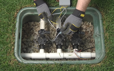
For wires not buried in direct soil contact: use a grease-filled wire nut. Strip the wire ends — keep the exposed length shorter than the depth of the nut — twist the conductors together, and screw on the nut. The grease fills the air space and blocks moisture.
For direct-burial splices: use a direct burial splice connector. The wire ends go into a grease-filled tube rather than an open cap, and the tube seals when closed. This provides a fully waterproof joint rated for continuous soil contact.
For both splice types: tape the wires together below the splice as a secondary mechanical connection. This prevents the splice from being stressed if the wire is pulled or shifted during future work.


